RESULTS
DETERMINATION OF STRONG MAGNETIC FIELD IN THE RANGE OF 1- 6 kGauss
-
An oscilloscope is used to record the transmission spectrum of laser radiation, which passes through a nanocell with a thickness of L = 398 nm (Rb D1 line), a longitudinal magnetic field is applied (laser polarization is sigma+). The oscillogram (and its data file) are transferred to the computer. With the help of a computer program (which is now being developed by Apet Sarkisyan), the distances a = (x1-x10) and b = (x1-x2) are measured, then the ratio a / b is determined.
Using the ratio a / b the curve in Fig. 2 is used to determine the magnitude of the magnetic field. To avoid misunderstanding, we note: we set the numbering 1and 2 because they have the highest frequency (as is customary in the literature), however, in the data file (from Fig. 1), the first transition is number 10, transitions 1and 2 are at the very end of the data file. According to the program in the data file, in the initial part there is a transition at number 10 (the largest peak A10) and its coordinate x10, then there is the largest transition at the end in the data file at number 1 (the largest peak A1) and its coordinate x1. Next, there is the largest penultimate transition in the data file at number 2 (the largest peak A2) and its coordinate x2. Next, the ratio (x1-x10) / (x1-x2) is built. Further, according to the data file from Fig. 2, the magnetic field value is determined.
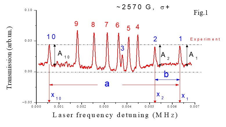
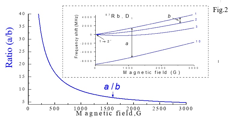
From the oscilloscope, the spectrum is fed to the computer and there is a data file. The computer program will give the values a = (x1-x10) and b = (x1-x2), the ratio a / b and then the magnitude of the magnetic field is determined according to the curve Fig.2. It is expected that the first stage processing will be 1 second. This is a method where you do not need to have a reference spectrum to determine the magnetic field! It is important to note that up to 6000 Gauss fields, transitions 1, 2 and 10 do not overlap with other atomic transitions.
Ambient field compensation
-
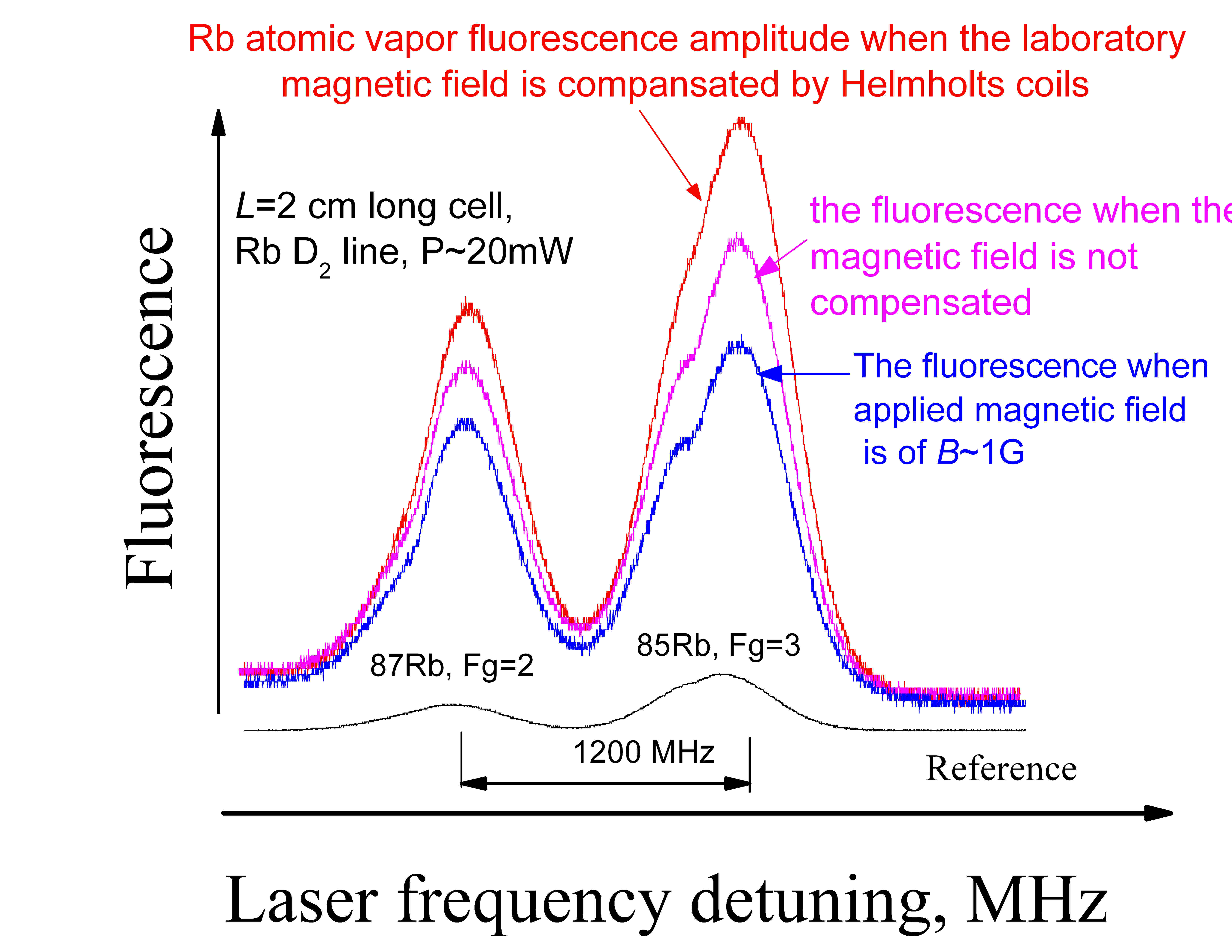
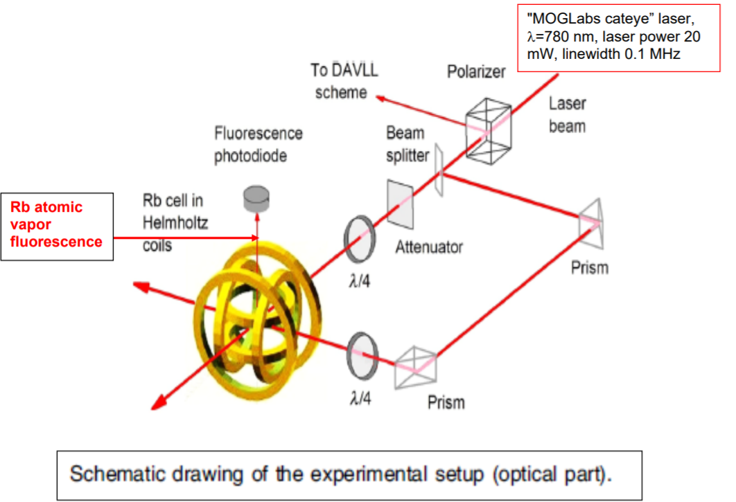
Fluorescence amplitude is shown in the figure, when the laboratory ambient magnetic field is compensated by Helmholz coils using three independent electric currents. Experiments were performed on Rb D2 line, using 780 nm laser light.
Experimental setup is shown below.
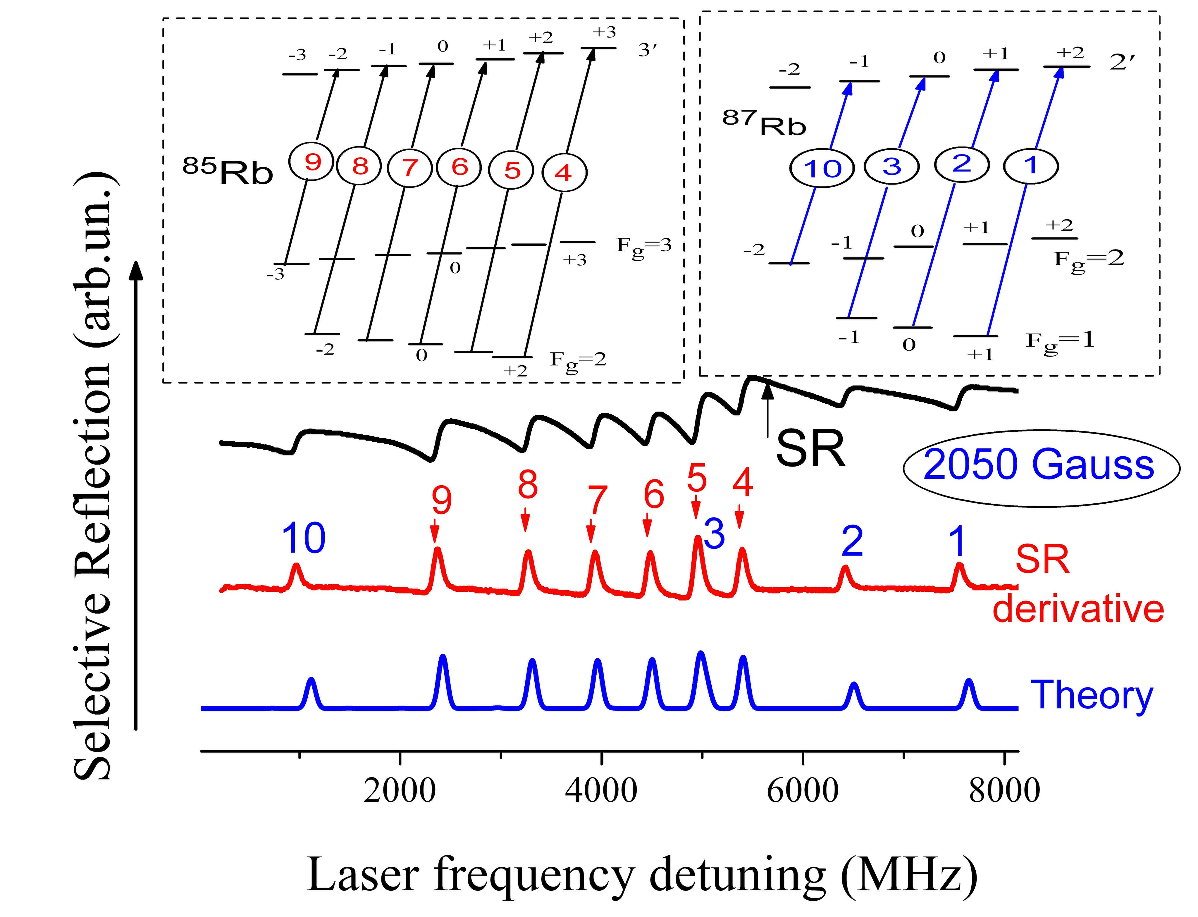
Selective reflection experiments
-
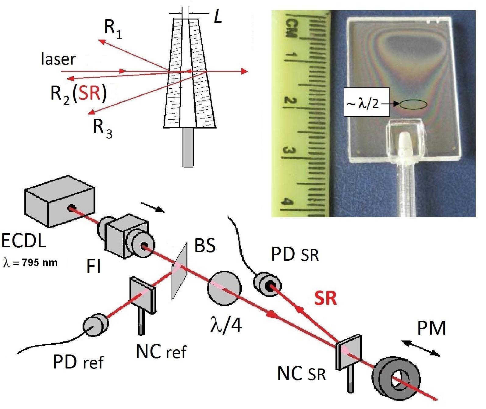
Selective reflection experiments have started. The experimental setup is shown below.
Experimental spectra and corresponding theory are shown below.